


Rainwater Harvesting 1:
Philippine Rooftop Rainwater Catchment System
I want to share with you how we designed our rainwater catchment system here on our homestead farm in the Philippines. It's a bit long but maybe it could help someone. A rainwater system can be very simple but if you want to capture the maximum amount of water possible, say you're off-grid or using it for agriculture, it's best to design it well.
I'm not an expert, nor a plumber nor an architect (and often these people don't even follow the standards regarding rainwater), just someone who studied up a lot on it and got good advice from an expert. I may have some things wrong. Please do your due diligence.
GUTTER DESIGN
The rainwater system should be designed so that your roof and gutters all drain without overflowing during a minimal 1:20 Average Recurrence Interval (ARI).
Average Recurrence Interval (ARI) means the long-term average number of years between the occurrences of a flood as big as or larger than, the selected event. For example, floods with a discharge as great as, or greater than, a 20 year ARI rain intensity statistically occurs every 20 years. ARI is another way of expressing the likelihood of occurrence of a flood event.
It’s important to know your rainfall intensity so that your system isn’t overwhelmed by large storms. After much digging on the internet we found a document showing rainfall intensity and chose a site about 30km NW of us, Ambulong (Figure 1).

From this, we used the average rain intensity over a 5 minute duration (29.84mm/5 minute). Considering these figures are a little out of date already, you could possibly add a 20% safety factor to it.
Also take note of your average annual precipitation as it may help you in sizing your tank volume. For our area, the precipitation averages 1904 mm (Tropical Monsoon Climate) [from: https://en.climate-data.org/location/20576/].
The way you go from here depends on whether you are building from scratch or modifying something already installed. For us, our gutters and downpipes were already installed so these calculations were a check on their capacity and also to design the piping that would run to the tank.
If you measure the profile of your gutters you can roughly calculate their capacity (See Figure 2).

The gutters should be installed with a slight down slope (recommended minimum of 1:350) towards each downpipe.
You should measure the size of the holes in the bottom of the gutters where the water drains. This is known as the "pop". They are usually spaced about every 6m but with your calculations you can determine if they safely drain the roof area above them.
Make a scaled drawing of your roof and calculate areas for each section of roof draining to each downpipe (Figure 3).
Also determine the pitch of your roof (its slope). Roof pitch is subject to a multiplier to determine a factored (greater) roof area to allow for more wind driven rain falling on one side of the roof.
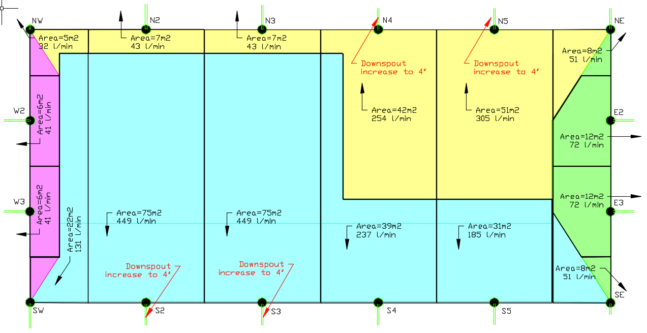
We can now determine the captured rainfall for each side of the house. For the north side the total roof area is 118m2. The captured rainfall per minute will be
(Area) x (5 minute ARI) / (5 minutes)118 x 29 / 5 = 704 L/minIf we include wind driven rain we have to add a factor that depends on the slope of the roof and also depends on whether the roof butts up against any vertical walls. The factor is found in the Australian and New Zealand standards on Stormwater Drainage (AS/NZS 3500.3 - I found an old 2003 copy on the internet). I’ve included this in Figure 4.

Putting this in a table we get Figure 5. I’ve taken the total roof areas for each side of the house, multiplied this by the 5 min ARI to get the captured rainfall. Then I’ve also applied the multiplier from AS/NZS 3500.3:2003 Table 3.2 depending on the average slope of that section of roof to get the wind driven rain captured.

The roof multiplier factors wind driven rain but the total roof area does not collect more water than a flat roof would. Depending on wind direction during severe winds, a lot of the water draining from the upper roof will probably never reach the lower roof and a lot of water falling on the lower roof would also be blown off. The real test will come with heavy rain when the wind has dropped.
The next step is to determine if our already installed gutter “pops” will drain the roof. We have 16 of these “pops” spaced fairly evenly around the perimeter. How much water they can drain is calculated using the Australian and New Zealand standards on Plumbing and Drainage (AS/NZS 3500.1 - I found an old 2003 copy on the internet) Table 8.3. This shows the rate of drainage from a vertical pipe (Figure 6). This is how you determine how many litres per minute each “pop” of the downspout can drain.
Please note, this calculation is not exact, but a good approximation. Figure 6 is for a tank with still water. The water in your gutter will be flowing and so behaves differently. The most important thing to know is that weir flow is greater when the water is higher.

My “pop” is 77mm diameter. The closest diameter in the table is 75mm. My “head” (height of water above crest of overflow) I chose to be 75mm. At worst it could be more than that but it has to be remembered that water in a gutter is not a solid mass (unlike water in a tank which is how the values in the standards are determined).
So for a “pop” of 75mm and a head of 75mm gives a flow rate of 3.22 l/s (or 3.22 x 60 = 193.2 l/min)
For the total drainage I multiply this by the 16 “pop”s.
Total drainage of all downspouts = 193.2 x 16 = 3091 litres per minute.As this result of 3091 l/min is greater than my calculated total captured wind driven rainfall of 2927 l/min then the roof will drain in a 1:20 storm event.
However, it is now important to check each downspout to see whether it can cope with the roof area draining into it. It’s great that the whole roof guttering can be drained in a storm but not so good if one side of the roof overflows while the other side drains adequately.
Working back, if we calculate the maximum area a 75mm “pop” can drain by dividing the flow rate by my areas’ 1:20 ARI. My ARI is 29.84mm/5 minute or 5.97mm/min.
Maximum roof area single downspout can serve = 193.2 / 5.97 = 32m2Looking at my roof plan in Figure 3 it can be seen that there’s quite a few downspouts that have larger roof areas, namely N4, N5, S2, S3, and S4. It may be the case that the gutters in these locations could possibly overflow. An option could be to increase the size of the “pop”, so cut a bigger hole in the gutter where the problem downspouts are.
RAINWATER STORAGE
Your storage options are dependent on the area you have available, the elevation difference available between your gutters and the top of the tank and of course your budget.
Regarding tank materials, I found an article from Milkwood in Australia:
This was very helpful but our choices in the Philippines differ quite a bit. Stainless steel tanks are very common here and are a good choice but are known to rust out quite quickly due to poor quality materials and maybe our acidic rains. Unlike in Australia, larger storage tanks here are very expensive and are usually more for industrial applications.
I found it difficult to determine what size tank I would need as it’s obviously useful to know your current water usage. As we were new to the property and had never farmed before, we had no idea of what our usage would be. So our size was based on what we could afford. In hindsight, it could have been smaller. We’ve never half emptied it but this is also because we farm in a water-smart way; regenerative grazing, heavy mulching, regular scything for year-round green grass and absorbent soils, double dug veggie beds. Our water needs are much smaller than a conventional farm of our size.
Our land is fairly flat apart from one side being steep down to a river 40m below. Our house has a very wide verandah and so our gutter height is quite low. This prevented me from choosing a large above ground tank as you need “head” (static pressure head) for the water to go from the gutter to the tank. So we decided on a concrete cistern-type underground tank as the solution. A benefit of this is that it saves space and is unobtrusive. You could build a bahay kubo or outside cooking area on it if you wanted. The disadvantages are that it’s difficult to drain for cleaning, can be damaged by tree roots or earthquake, risk of contamination is high, risk of accidental drowning, requires excavation costs and you need a pump to extract the water.
We use this cistern water exclusively for outdoor use, gardening and animal water so its cleanliness isn’t super important (but there are steps I can be doing to improve the cleanliness which I mention later). For drinking water we installed a seperate stainless steel tank under the verandah of the house which I will detail more later.
PIPING BETWEEN GUTTERS AND TANK
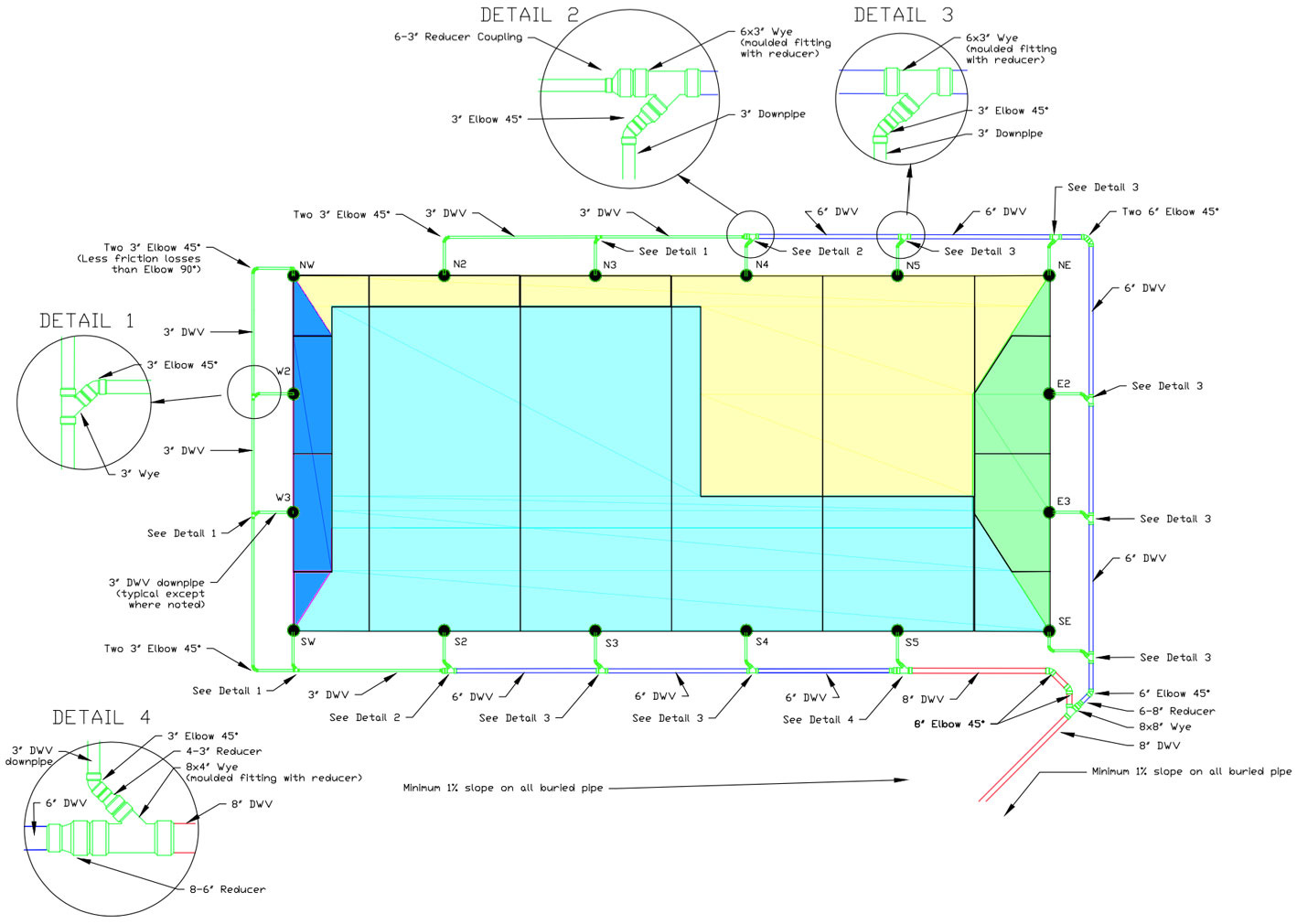
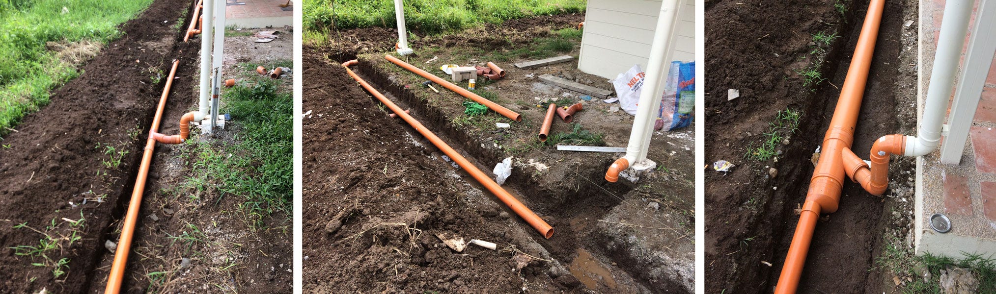
Since I have multiple gutters, I designed a ring-main piping system around the house to collect each downspout’s water and convey it to the tank some 44 metres away. All this piping needs to have a downward slope of at least 1%.
The builder had already installed 3” DWV downpipes. Figure 7 shows my design and what follows is how I calculated pipe sizing.
To calculate pipe sizes I used the following online calculator:
Gravity Fed Pipe Flow: http://www.calctool.org/CALC/eng/civil/hazen-williams_g
My pipes start at 3” which has a nominal internal diameter (ID) of 0.077m. You often find the nominal internal diameter of your pipes on the manufacturer’s website or measure it yourself. Yours may differ from mine.
Roughness coefficient of 150 (plastics).
Pipe length is 6m between downspouts.
The drop, because I have a 1% downward slope, will be 0.06m.
This gives a discharge rate of 245 litres/minute.
The velocity of the water in the full pipe will be 0.88 metres/second. Friction losses increase exponentially to the velocity and will affect your static head (see below).
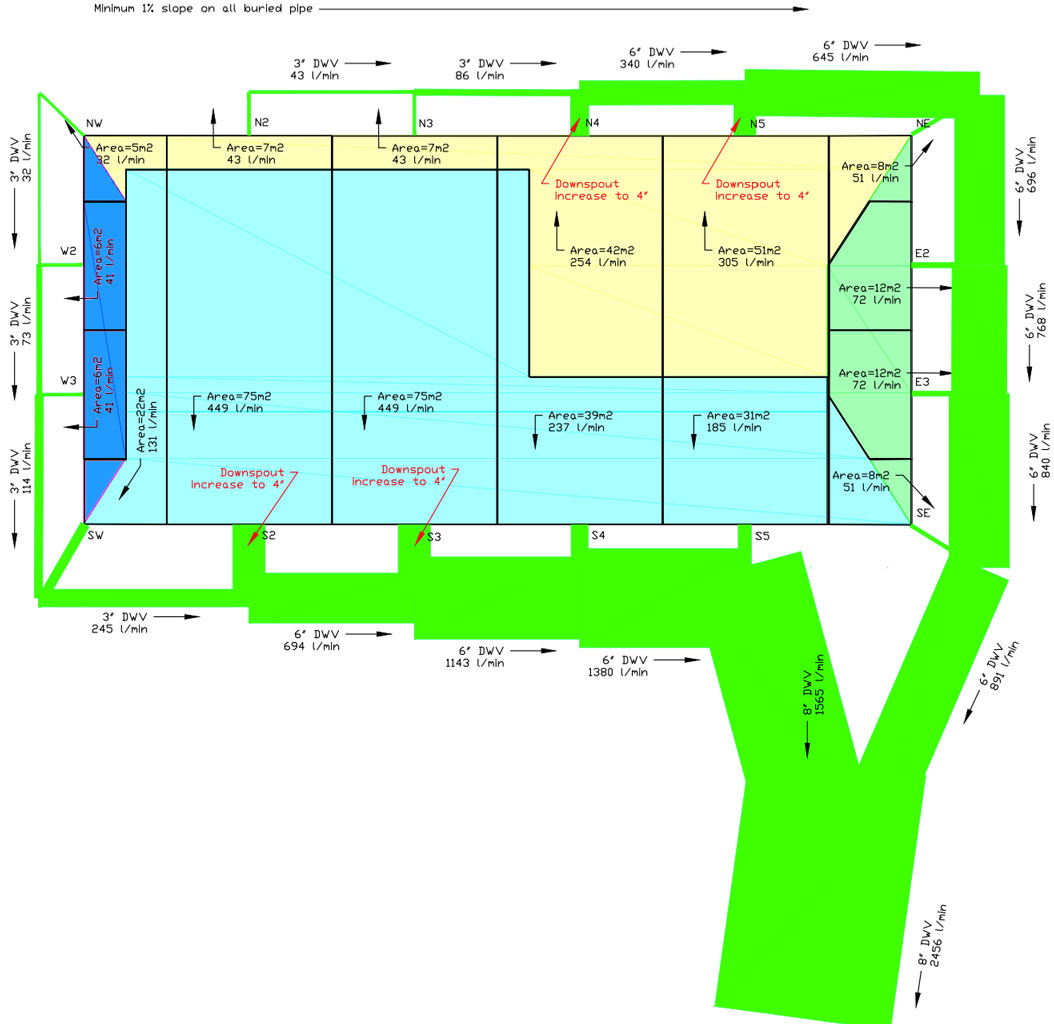
Looking at Figure 7, I have a pipe running around the west and south of the house (servicing downspouts NW, W2, W3, SW, S2, S3, S4 and S5). A second pipe runs from the north downspouts and also services the east downspouts. Both meet up in a Wye join at the south-east corner of the house and proceed towards the tank in one big pipe.
If we start at downspout NW we know in a 1:20 ARI storm that it will have 32 litres/minute. My 3” pipe can carry a maximum of 245 litres/minute. So that’s good.
This 3” pipe then joins up with the water flowing off downspout W2 (41 litres/minute in a 1:20 ARI storm). So after W2 my pipe needs to carry 32 l/min + 41 l/min = 73 litres/minute. This is still less than the capacity of my 3” pipe so it continues on this next section. This continues past downpipes W3 and SW, at which point the flow rate has accumulated to 245 l/min (32 NW + 41 W2 + 41 W3 + 131 SW). This is now equal to the discharge rate of a 3” pipe.
This 3” pipe then joins up with the water flowing off downspout S2 (449 litres/minute in a 1:20 ARI storm). So after S2 my pipe needs to carry 245 l/min + 449 l/min = 694 litres/minute. This is too much for a 3” pipe (max 245 l/min), so I go back to the online calculator and work out the discharge rate of a 4” pipe:
4” DWV pipe has a nominal internal diameter of 0.099m.
Roughness coefficient of 150 (plastics).
Pipe length is 6m between downspouts.
The drop, because I have a 1% downward slope, will be 0.06m.
This gives a discharge rate of 475 litres/minute.
Velocity of water in a full pipe will be 1.03m/s.
This is still too small to carry my 694 litres/minute so I go back to the online calculator until I find that a size of 6” is enough (they don’t make 5” DWV pipe in case you’re wondering):
6” DWV pipe has a nominal internal diameter of 0.15m.
Roughness coefficient of 150 (plastics).
Pipe length is 6m between downspouts.
The drop, because I have a 1% downward slope, will be 0.06m.
This gives a discharge rate of 1419 litres/minute.
Velocity of water in a full pipe will be 1.34m/s.
This is enough and even at downspout S3, which adds another 449 l/min bringing the storm flow rate to 1143 litres/minute, the 6” DWV pipe will be adequate. This is continued for the rest of the piping, ensuring that each can carry the accumulated storm flow. The resulting piping diagram is shown in Figure 8.
The next step I took was to calculate the required “head”. This is the difference in height between the bottom of the downspout rainhead (the “leaf eater” as I mention later) and the inlet of the tank. Obviously, if they were both at the same elevation, the water would not flow into the tank. Put the tank inlet at a lower elevation, the water will then flow into the tank. But with long pipes and high flow rates, the friction of the pipe will affect how much head you need for the water to flow into the tank. A video demonstrating the friction losses is:
Many articles incorrectly generalise and say you need a head of at least 300mm. However since I have high flow rates and large pipes I began calculating the friction losses along the length of all our pipes and all the fittings. For friction losses in fittings (elbows and tees, etc) I used the tables below to give an equivalent length of straight pipe:
https://www.engineeringtoolbox.com/equivalent-length-copper-pipe-fittings-d_1670.html
For friction losses I used the calculator at:
https://www.engineeringtoolbox.com/hazen-williams-water-d_797.html
Or alternatively:
https://www.nationalpump.com.au/calculators/friction-loss-calculator/
My theoretical result was a head of approximately 600mm. Since this is much less than my elevation difference between leaf eater and tank inlet, the water will flow into the tank.
Please note: each downpipe charges the carrier pipe with each successive downpipe acting as a water tower to recharge the carrier pipe’s pressure drops caused by friction losses. This effectively lessens the pipe’s full flow friction losses. These calculations are again, a good approximation but not exact. The downpipes have plenty of capacity to boost the carrier pipe’s discharge during heavy rain when the pipes are full.
WATER CLEANLINESS
It’s important to take steps to keep solids out of the catchment system.
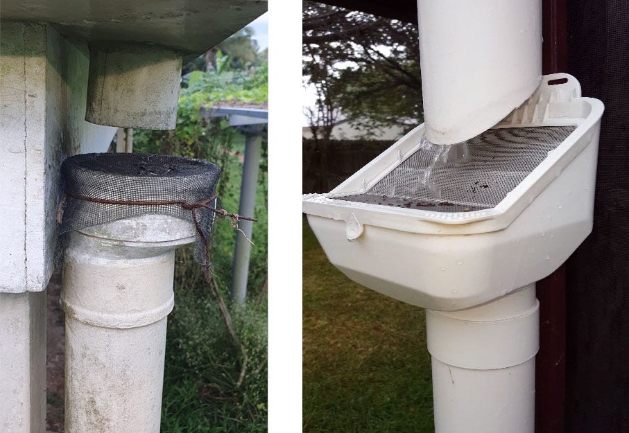
To keep leaves and other gutter rubbish from going into our tank we use insect screening on top of each downpipe (Figure 10). It’s critical to use insect screening on all pipes to the tank to prevent mosquitos. The simple design is based on commercial leaf diverters which can cost quite a bit if you have many downspouts. One day I may modify mine to have a slope, I have to regularly clean the leaves off mine which is tolerable since I can still reach it without a ladder. The insect screening will reduce your flow rate and head but this can be fixed by installing a low restriction inlet on your tank (which I’ll describe later).
A leaf diverter also acts as an air gap to prevent the gutter back filling during a severe storm.
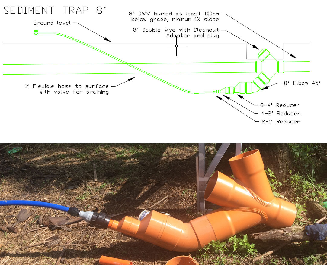
Despite leaf-eaters on downspouts, you will still get sediment in your water (from airborne dust) so it is necessary to have a sediment trap or some sort of first flush system. Often first flush systems are poorly designed and waste a lot of water without actually doing their intended job. First flush systems are for “dry systems”, where the water in the pipes is emptied by gravity after each rainfall.
As we have a “wet system” (there will always be water present in the piping which can stagnate between rains) we use a sediment trap to allow solids in the piping to be flushed out. I copied a design online (which I believe SaveH2O may have designed, see notes at end) and placed the sediment trap towards the tank (Figure 11). It’s important that it is placed about 2-3m after the last bend or tee joint (to allow the solids to settle).
Sediment traps make a huge difference to the water cleanliness and this design is simple and doesn’t waste a lot of water. Suspended sediment settles as bed load and bed load remains mostly stationary with occasional movements. Gravity then takes over to trap it.
Unfortunately due to the lay of our land, to drain the sediment trap would mean running the 1” pipe over 130m to a lower part of our property. So I don’t flush the traps as often as I should, I attach a pump and pump it out every 6 months or so. This means that water in my pipes stagnates during dry periods, causing very poor water quality. My future plan is to run this flexible hose to my tank’s overflow pond which I hope to dig deep enough in order to drain the sediment trap.
TANK
We had an underground cistern built with a capacity of 100 cubic metres (100,000 litres). When designing a large tank ensure there are multiple access points and air vents. The air vents can double as a place to measure your water. There is no need to ever enter the tank, it is a confined space and specialised training and rescue equipment is needed to be on standby. This is the same for wells and big above ground tanks. Never enter one unless you have the training, equipment and back up.
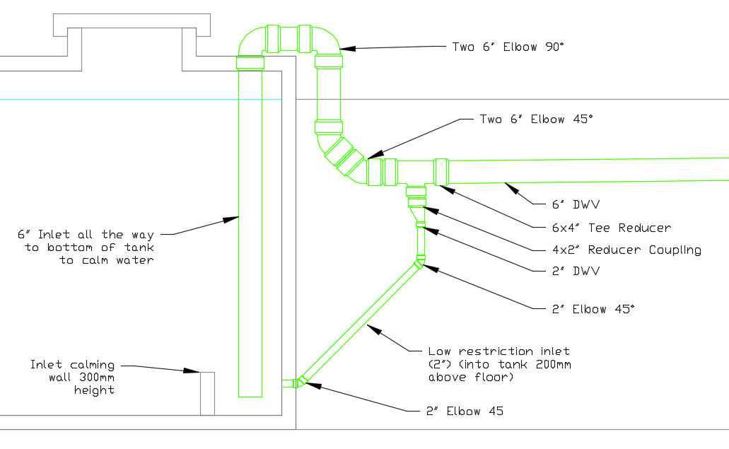
The water inlet for our tank is shown in Figure 12. The reason for having the inlet piping all the way down to the cistern floor, and the inlet calming wall, is to prevent disturbing the sediment layer inside the tank. Any tank will naturally get a sediment layer and this is perfectly normal and once settled will not affect your water quality. The idea is not to disturb that layer when water is going in, and when you are pumping it out.
The low restriction outlet is a smaller pipe branching off the vertical riser’s base and diverting to a low inlet. It provides a higher velocity low restriction flow path for any small bits of heavier debris. The normal flow velocity up a vertical riser is unable to do this, the reason why debris accumulates in standard wet system’s horizontal pipes. This low restriction inlet needs to be sized to suit the system. If the level of water in the tank is below the carrier pipe, it will drain completely and become a “dry system”.
Water flowing through a low restriction inlet oxygenates the tank's anaerobic zone and reduces the height of the water retained in the vertical riser and downpipes. A low restriction inlet operates with greater head pressure than water flowing up a vertical riser due to the height difference between the level of water in the tank and the height of the water in the vertical riser. This gives the low inlet priority flow which supplements the vertical riser's flow capacity, solving a common problem when fitting leaf diverters that result in insufficient head.
Every tank must be fitted with an overflow pipe. Ours flows into a small hand-dug unsealed pond. It is a good idea to install some sort of flap on the overflow so that rats and lizards can not crawl inside. Your overflow pipe needs to be correctly sized.
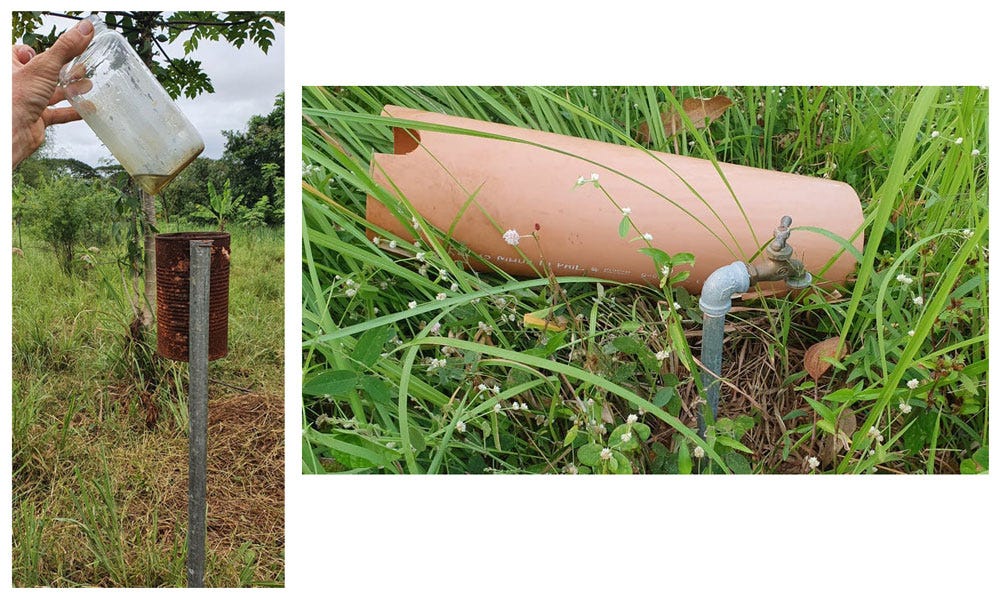
To draw water out of the tank it’s best to pump from about 30cm below the surface of the water level. This is so you don’t draw out the dust that sits on top of the water and you don’t get the sediment at the bottom of the tank. Simple way to do this is to tie the float from a float valve to the end of the pipe inside the tank. We use a pump to draw the water out to an elevated tank. I've run a ring main around the farm with taps positioned such that a 30m garden hose can be attached and water everything on the property. Although this took some time to set up, it saves a lot of time now carting water everywhere. Each of the taps I cover with leftover DWV pipe so that it’s easy to spot when grass cutting (Figure 13).
MEASURING RAINFALL
I grew up on a farm, and many conversations between my parents and other farmers often involved rain, how much did you get, how long since the last rain. So not surprisingly I see great importance in capturing rain, even in a tropical country.
Measuring rain is simply a glass jar on a pole, situated away from the house and any trees. Measuring the height of the rain in the jar will basically give you the number of millimetres of rain that’s fallen. As I’m fairly pedantic I weigh the water in the jar to get a more accurate result and divide it by the jar’s bottom area. After the rainfall I also measure the volume of water in the tank.
I keep a spreadsheet of rainfall, tank volume and usage. Figure 14 shows the rainwater statistics from 2020 which was a particularly wet year. If you want a copy of my spreadsheet, though it might be a bit confusing to anyone other than me, just message me.
As you can see, our tank volume didn’t drop more than ¾ full (the orange line), so I can afford to use a lot more water during the hot, dry summers for our plants. I’ll discuss this more another time with details of our management to save, slow down and sink water on our land using plants.

I found average rainfall statistics for our area from the internet to compare to our actual rainfall. I’m sure PAGASA (Philippine Atmospheric, Geophysical and Astronomical Services Administration) has better data but I don’t think it’s freely available to the public? See Figure 15.

DRINKING WATER
We have a seperate 1000L stainless steel tank located under the eaves of our verandah. This is a good example of how simple your rainwater system can be. The tank is out of direct sunlight and weather and always sealed unless it is being filled (Figure 16).
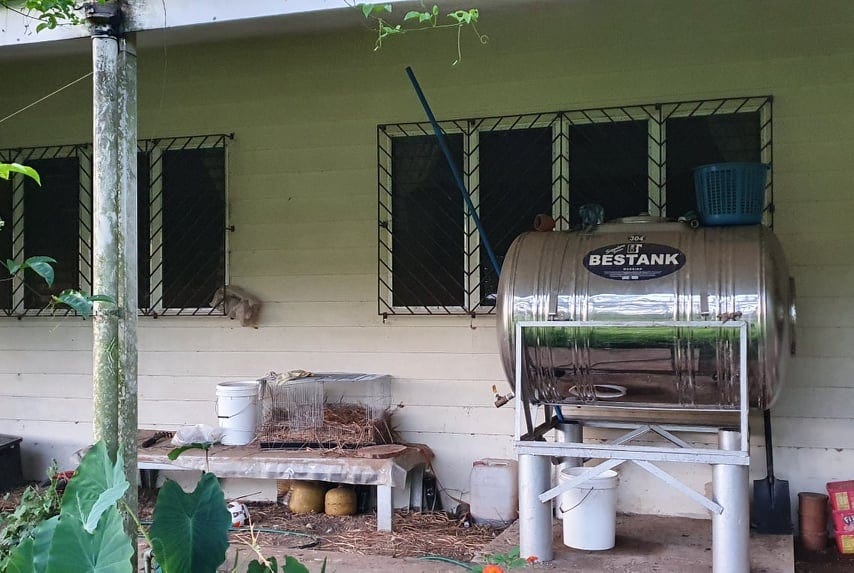
It is located close to the house downpipe with the strongest flow. During a strong downpour I simply connect a pipe from a hole below the downpipe’s leaf diverter to the tank. The water is pretty clean because of the insect screening and because I only connect the pipe once the water flow is strong, so the roof is already cleaned of the initial dust and gutter debris. If there is any sediment it falls to the bottom of the tank after a day. I clean out the tank once every rainy season when there is a good chance to fill it again within a week.
I used to drink the water directly from the tank but we realised the rain in our area may be more acidic than normal due to the Taal volcanic activity (and maybe not coincidentally we’ve had a few family dental issues in the past few years!). Rain is naturally slightly acidic and it’s best to place a piece of limestone in the tank to neutralise it. This will possibly prolong the life of your tank too. We now use an off-the-shelf drip water filter which also does the job of neutralising it. If you use a concrete tank, the water will absorb some of the minerals out of the concrete and will generally settle in a slightly alkaline state.
An inventor here in the Philippines has developed an expandable rainwater storage and filtration system and if you’re at all interested in using the rain, his system is worth checking out. See Dr Mateo on Facebook: https://web.facebook.com/antonio.f.mateo.
A slideshow presentation showing the system is here: http://www.aisf.or.jp/sgra-in-english/seminar14/DrAntonioMateo.pdf
It’s possible to build your own water filtration system (it’s on my to-do list). Two resources worth checking out regarding this are as follows:
Aqueous Solutions - Josh Kearns has done much valuable work in SE Asia building water filtration systems in far flung villages and helping many poverty stricken people get access to clean healthy water. His systems use biochar which is easily created using a DIY kiln. We used his kiln design and now make regular biochar from our coconuts shells/husks and fallen timber after each typhoon passes through. I’ll detail more about this another time. https://www.aqsolutions.org/
Biosand filter - is an adaptation of the traditional slow sand filter, which has been used for community drinking water treatment for 200 years. https://www.cawst.org/services/expertise/biosand-filter/more-information
Of course the best “solution” for poor quality water is to restore ecological function to our land. Water Stories is a group set up by Zach Weiss (protégé of Sepp Holzer and expert in water retention landscapes). If you’re interested in learning how water is probably the biggest driver of climate and what we can do about it, join: https://community.waterstories.com/share/iyukx6pTdEyA-uAP?utm_source=manual
NOTES
I’ve been meaning to write this up for a long time, but what kicked me into gear was reading “Water in Plain Sight” by Judith D. Schwartz. A very inspiring book which should be compulsory reading for everyone. She has reminded me of this; “What's been missing in the climate change conversation is the primacy of ecosystem processes in climate regulation. We know we can rehabilitate even the most degraded ecosystems, and so we can help reinstate that regulation capacity”. Judith is brilliant at communicating these ideas.
The rooftop rainwater harvesting system I’ve detailed above is only one part of our water management on our land. I hope to post some more in the future about how we manage water on our landscape. We are striving to restore ecological function to our land, working with nature and not against it. A common mantra regarding rainwater is “Slow it. Spread it. Sink it. Store it.”
Nearly all of this post was written with knowledge I gained through the generosity of one anonymous person on an Australian building forum. If you are interested in designing your own rainwater system I encourage you to research the information posted by “SaveH2O” on the homeone.com.au forums. Most of the rainwater topics are under the “eco living” sub-forum. If I have made any errors here, they are mine, not his.
There are many ways to capture rainwater, this is ours. Thanks for reading this far.
Version 2, 1 March 2022 (Clarifications made with help from SaveH2O)
Ver. 1, 20 February 2022
Water filtration system designs (thanks Aqueous Solutions):
1. 2000 Liter per day (“PunPun”) Water Treatment System Graphical Manual:
https://www.aqsolutions.org/wp-content/uploads/2020/04/2000LPD_English.pdf
2. 300 Liter per day (“blue barrel”) Water Treatment System Graphical Manual:
https://www.aqsolutions.org/wp-content/uploads/2020/04/blue-barrel-system-manual-English.pdf
3. Joy Barrett’s 1991 Manual of Design for Slow Sand Filtration : https://www.joinforwater.ngo/sites/default/files/library_assets/353.1_HEN_E5_Manual_Design.pdf.pdf
State Secretary Martin Kováč and Water Resource Advisor to the Prime Minister of Slovakia Michal Kravčík prepared a concise, comprehensive document which describes recommendations for the UN 2023 Water Conference Water for Climate Healing – A New Water Paradigm White Paper.
https://www.mpsr.sk/en/index.php?navID=54&id=84